New Product · Aamtron Group — Middle East Distributor
SecureAir Modular Aluminium Compressed Air Piping — Qatar & UAE
The complete SecureAir aluminium air-line system: calibrated pipe, push-together fittings, valves, flanges and accessories from 20 mm to 200 mm. Leak-free, corrosion-free and engineered to ASME B31.1 & B31.3 — supplied and installed across Qatar & UAE.
Quick Answer
SecureAir is a modular aluminium compressed air piping system supplied by Aamtron Group across Qatar, UAE, Saudi Arabia and Oman. The range covers calibrated aluminium pipe (20–200 mm), push-fit connectors, elbows, tees, drop lines, ball & butterfly valves, threaded adaptors, flanges, seals and a full accessory set — all leak-free, corrosion-resistant and rated to 16 Bar. Use the diameter selection chart below to size your ring main, then request a quotation.
A faster, cleaner, leak-free compressed air network
SecureAir replaces traditional welded GI and black-steel air lines with a lightweight, modular aluminium system that installs in a fraction of the time. Calibrated pipe and precision fittings simply push together with O-ring seals — no welding, no threading, no rust, no pressure-drop from internal corrosion.
The system carries compressed air, nitrogen, vacuum and inert gases, and is fully demountable and reconfigurable as your plant layout changes. Aamtron Group is the Middle East distributor, holding stock and providing design, sizing and turnkey installation across Qatar and the UAE.
20mm – 200mmUp to 16 BarASME B31.1 & B31.3350+ SKUs in stockLeak-free O-ring seals
Quality & Durability
Corrosion-resistant, high-strength calibrated aluminium that won't rust or contaminate the air stream.
Leak-Free Assurance
Engineered O-ring connections tested for zero-loss performance — no compressed air wasted.
Faster Installation
Easy-to-fit modular push system. No hot work, no welding permits, fully demountable.
Widest Range
One complete catalogue from 20 mm to 200 mm — pipe, fittings, valves, flanges and accessories.
Trusted Support
350+ SKUs held in stock by Aamtron Group with quick deliveries across Qatar & UAE.
Built for Industry
Automotive, pharma, food & beverage, textiles, manufacturing, warehousing and logistics.
Product Catalogue
Every product below shows its Sr No, Item Code, sizes (ID/OD/length or L·W·H), dimensions and engineering drawing exactly as specified. Item-code prefixes act as your ordering reference.
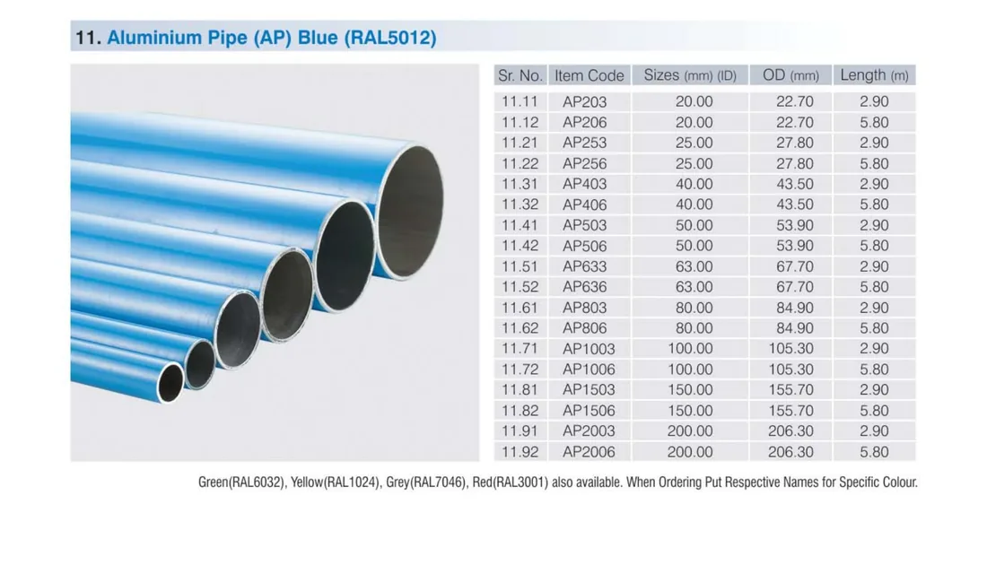
1. Aluminium Pipe (AP)
RAL5012 Blue standard. Also available in Green (RAL6032), Yellow (RAL1024), Grey (RAL7046) and Red (RAL3001) — state the colour when ordering.
Aluminium Pipe — Sizes, Outer Diameter & Length
Sr No
Item Code
Size — ID (mm)
O.D (mm)
Length (m)
11.11
AP203
20.00
22.70
2.90
11.12
AP206
20.00
22.70
5.80
11.21
AP253
25.00
27.80
2.90
11.22
AP256
25.00
27.80
5.80
11.31
AP403
40.00
43.50
2.90
11.32
AP406
40.00
43.50
5.80
11.41
AP503
50.00
53.90
2.90
11.42
AP506
50.00
53.90
5.80
11.51
AP633
63.00
67.70
2.90
11.52
AP636
63.00
67.70
5.80
11.61
AP803
80.00
84.90
2.90
11.62
AP806
80.00
84.90
5.80
11.71
AP1003
100.00
105.30
2.90
11.72
AP1006
100.00
105.30
5.80
11.81
AP1503
150.00
155.70
2.90
11.82
AP1506
150.00
155.70
5.80
11.91
AP2003
200.00
206.30
2.90
11.92
AP2006
200.00
206.30
5.80
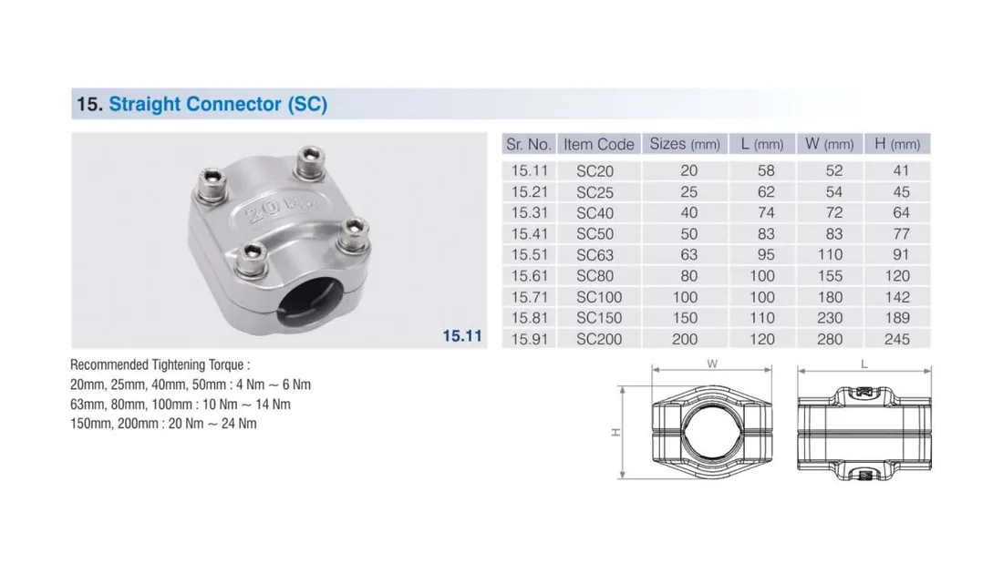
2. Connectors
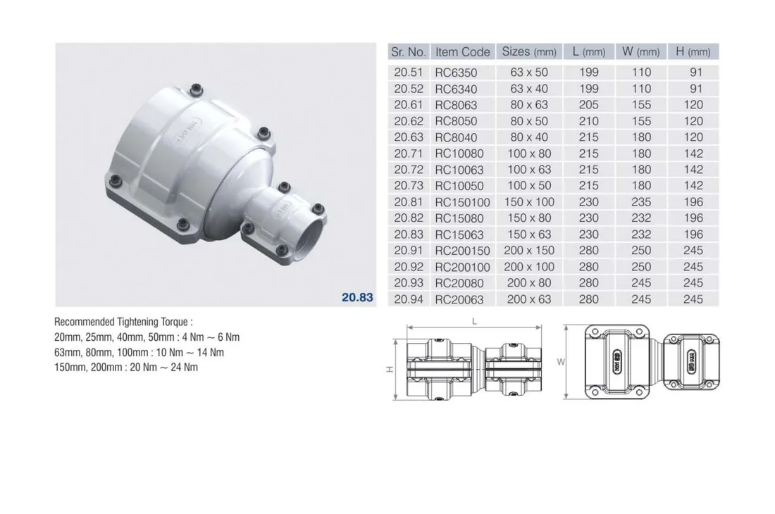
Recommended tightening torque: 20–50 mm = 4–6 Nm · 63–100 mm = 10–14 Nm · 150–200 mm = 20–24 Nm.
Straight Connector (SC)
SC · 20–200mm
Couples two equal-diameter pipes.
Sr No
Item Code
Size (mm)
L (mm)
W (mm)
H (mm)
15.11
SC20
20
58
52
41
15.21
SC25
25
62
54
45
15.31
SC40
40
74
72
64
15.41
SC50
50
83
83
77
15.51
SC63
63
95
110
91
15.61
SC80
80
100
155
120
15.71
SC100
100
100
180
142
15.81
SC150
150
110
230
189
15.91
SC200
200
120
280
245
Product photo & technical drawing
Reducer Connector (RC)
RC · 25×20–200×63
Couples two different diameters.
Sr No
Item Code
Size (mm)
L (mm)
W (mm)
H (mm)
20.21
RC2520
25 × 20
60
54
45
20.31
RC4025
40 × 25
73
72
64
20.32
RC4020
40 × 20
75
72
64
20.41
RC5040
50 × 40
74
83
77
20.42
RC5025
50 × 25
79
83
77
20.43
RC5020
50 × 20
79
83
77
20.51
RC6350
63 × 50
199
110
91
20.52
RC6340
63 × 40
199
110
91
20.61
RC8063
80 × 63
205
155
120
20.62
RC8050
80 × 50
210
155
120
20.63
RC8040
80 × 40
215
180
120
20.71
RC10080
100 × 80
215
180
142
20.72
RC10063
100 × 63
215
180
142
20.73
RC10050
100 × 50
215
180
142
20.81
RC150100
150 × 100
230
235
196
20.82
RC15080
150 × 80
230
232
196
20.83
RC15063
150 × 63
230
232
196
20.91
RC200150
200 × 150
280
250
245
20.92
RC200100
200 × 100
280
250
245
20.93
RC20080
200 × 80
280
245
245
20.94
RC20063
200 × 63
280
245
245
Product photo & technical drawing
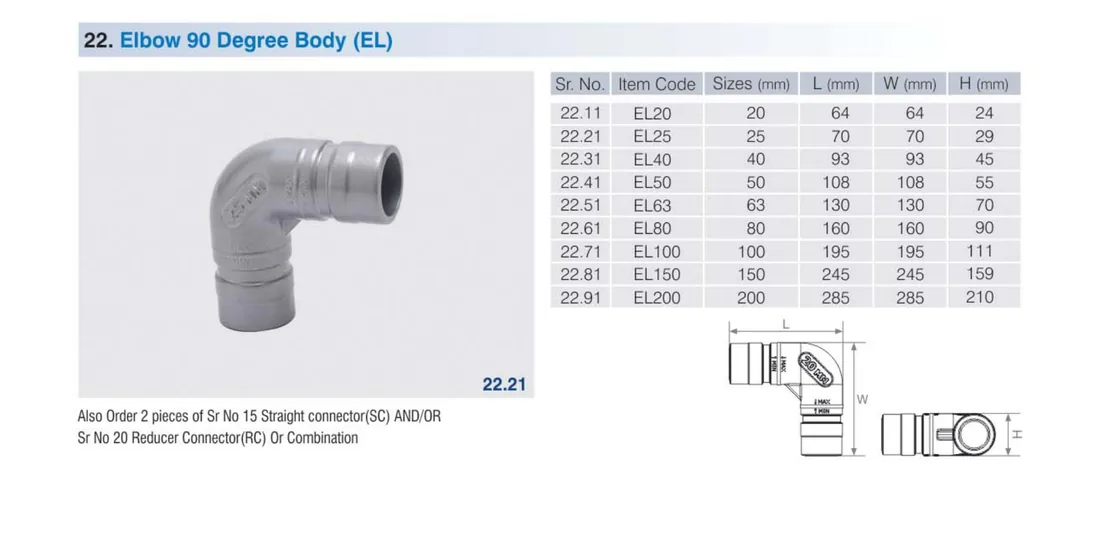
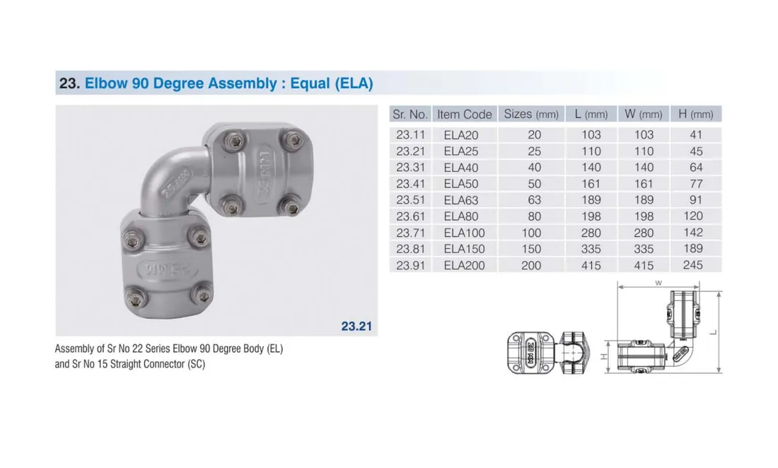
3. Elbows
Bodies (EL / EH) order with 2× SC or RC connectors. Assemblies (ELA / EHA) come pre-fitted with straight connectors.
Elbow 90° Body (EL)
EL · 20–200mm
Sr No
Item Code
Size (mm)
L (mm)
W (mm)
H (mm)
22.11
EL20
20
64
64
24
22.21
EL25
25
70
70
29
22.31
EL40
40
93
93
45
22.41
EL50
50
108
108
55
22.51
EL63
63
130
130
70
22.61
EL80
80
160
160
90
22.71
EL100
100
195
196
111
22.81
EL150
150
245
245
159
22.91
EL200
200
285
285
210
Product photo & technical drawing
Elbow 90° Assembly – Equal (ELA)
ELA · 20–200mm
Sr No
Item Code
Size (mm)
L (mm)
W (mm)
H (mm)
23.11
ELA20
20
103
103
41
23.21
ELA25
25
110
110
45
23.31
ELA40
40
140
140
64
23.41
ELA50
50
161
161
77
23.51
ELA63
63
189
189
91
23.61
ELA80
80
198
198
120
23.71
ELA100
100
290
290
142
23.81
ELA150
150
335
335
189
23.91
ELA200
200
415
415
245
Product photo & technical drawing
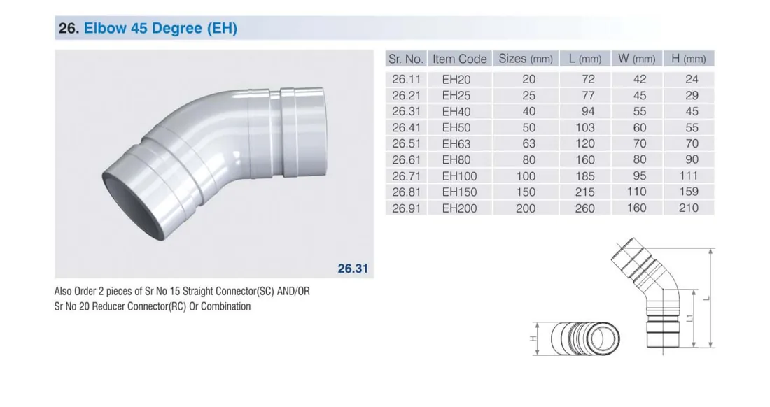
Elbow 45° Body (EH)
EH · 20–200mm
Sr No
Item Code
Size (mm)
L (mm)
W (mm)
H (mm)
26.11
EH20
20
72
42
24
26.21
EH25
25
77
45
29
26.31
EH40
40
84
55
45
26.41
EH50
50
103
60
55
26.51
EH63
63
120
70
70
26.61
EH80
80
160
80
90
26.71
EH100
100
185
95
111
26.81
EH150
150
215
110
159
26.91
EH200
200
260
160
210
Product photo & technical drawing
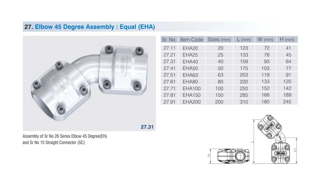
Elbow 45° Assembly – Equal (EHA)
EHA · 20–200mm
Sr No
Item Code
Size (mm)
L (mm)
W (mm)
H (mm)
27.11
EHA20
20
123
72
41
27.21
EHA25
25
133
78
45
27.31
EHA40
40
159
93
64
27.41
EHA50
50
175
103
77
27.51
EHA63
63
203
119
91
27.61
EHA80
80
220
133
120
27.71
EHA100
100
260
152
142
27.81
EHA150
150
285
166
189
27.91
EHA200
200
310
180
245
Product photo & technical drawing
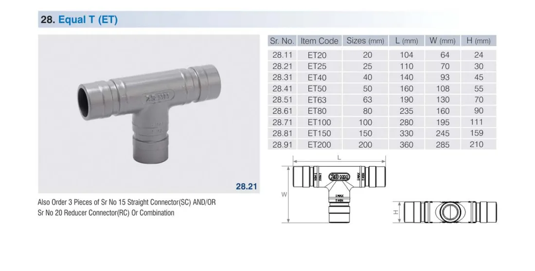
4. Equal Tees
Equal Tee Body (ET)
ET · 20–200mm
Order with 3× SC or RC connectors.
Sr No
Item Code
Size (mm)
L (mm)
W (mm)
H (mm)
28.11
ET20
20
104
64
24
28.21
ET25
25
110
70
30
28.31
ET40
40
140
93
45
28.41
ET50
50
160
108
55
28.51
ET63
63
190
130
70
28.61
ET80
80
235
160
90
28.71
ET100
100
280
195
111
28.81
ET150
150
330
245
159
28.91
ET200
200
360
285
210
Product photo & technical drawing
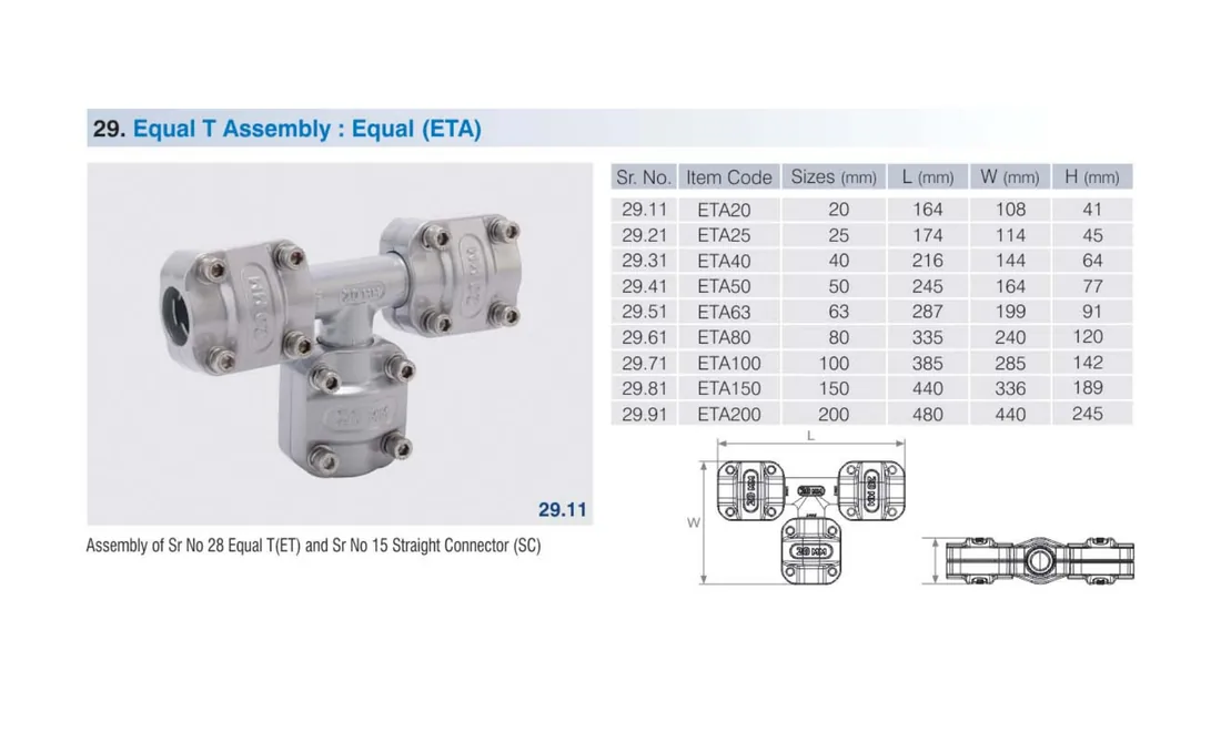
Equal Tee Assembly (ETA)
ETA · 20–200mm
Pre-fitted with straight connectors.
Sr No
Item Code
Size (mm)
L (mm)
W (mm)
H (mm)
29.11
ETA20
20
164
108
41
29.21
ETA25
25
174
114
45
29.31
ETA40
40
216
144
64
29.41
ETA50
50
240
164
77
29.51
ETA63
63
287
199
91
29.61
ETA80
80
335
240
120
29.71
ETA100
100
385
285
142
29.81
ETA150
150
440
336
189
29.91
ETA200
200
480
440
245
Product photo & technical drawing
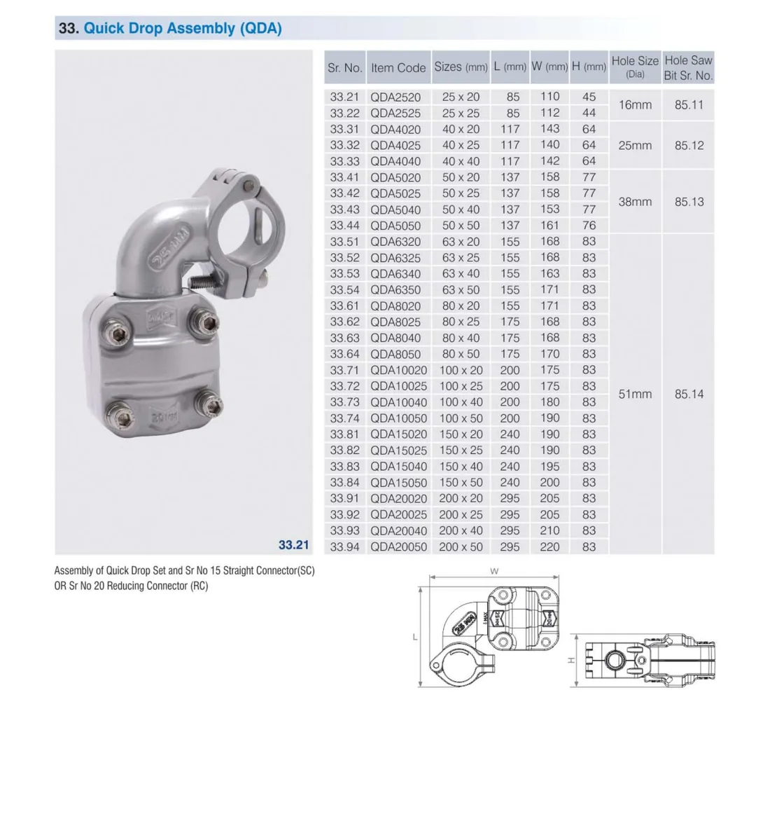
5. Quick Drop Outlets
Branch take-offs from the main ring, with the matching hole-saw bit reference (Sr No 85.11–85.14).
Quick Drop Assembly (QDA)
QDA · 25×20–200×50
Sr No
Item Code
Size (mm)
L (mm)
W (mm)
H (mm)
Hole Ø
Hole-saw bit
33.21
QDA2520
25 × 20
85
110
45
16 mm
85.11
33.22
QDA2525
25 × 25
85
112
44
16 mm
85.11
33.31
QDA4020
40 × 20
117
143
64
25 mm
85.12
33.32
QDA4025
40 × 25
117
140
64
25 mm
85.12
33.33
QDA4040
40 × 40
117
142
64
25 mm
85.12
33.41
QDA5020
50 × 20
137
158
77
38 mm
85.13
33.42
QDA5025
50 × 25
137
158
77
38 mm
85.13
33.43
QDA5040
50 × 40
137
153
77
38 mm
85.13
33.44
QDA5050
50 × 50
137
161
76
38 mm
85.13
33.51
QDA6320
63 × 20
155
168
83
51 mm
85.14
33.52
QDA6325
63 × 25
155
168
83
51 mm
85.14
33.53
QDA6340
63 × 40
155
163
83
51 mm
85.14
33.54
QDA6350
63 × 50
155
171
83
51 mm
85.14
33.61
QDA8020
80 × 20
155
171
83
51 mm
85.14
33.62
QDA8025
80 × 25
175
168
83
51 mm
85.14
33.63
QDA8040
80 × 40
175
168
83
51 mm
85.14
33.64
QDA8050
80 × 50
175
170
83
51 mm
85.14
33.71
QDA10020
100 × 20
200
175
83
51 mm
85.14
33.72
QDA10025
100 × 25
200
175
83
51 mm
85.14
33.73
QDA10040
100 × 40
200
180
83
51 mm
85.14
33.74
QDA10050
100 × 50
200
190
83
51 mm
85.14
33.81
QDA15020
150 × 20
240
190
83
51 mm
85.14
33.82
QDA15025
150 × 25
240
190
83
51 mm
85.14
33.83
QDA15040
150 × 40
240
195
83
51 mm
85.14
33.84
QDA15050
150 × 50
240
200
83
51 mm
85.14
33.91
QDA20020
200 × 20
295
205
83
51 mm
85.14
33.92
QDA20025
200 × 25
295
205
83
51 mm
85.14
33.93
QDA20040
200 × 40
295
210
83
51 mm
85.14
33.94
QDA20050
200 × 50
295
220
83
51 mm
85.14
Product photo & technical drawing
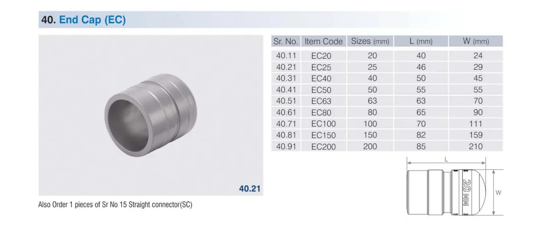
6. End Caps
End Cap (EC)
EC · 20–200mm
Sr No
Item Code
Size (mm)
L (mm)
W (mm)
40.11
EC20
20
40
24
40.21
EC25
25
46
29
40.31
EC40
40
50
45
40.41
EC50
50
55
55
40.51
EC63
63
63
70
40.61
EC80
80
65
90
40.71
EC100
100
70
111
40.81
EC150
150
82
159
40.91
EC200
200
85
210
Product photo & technical drawing
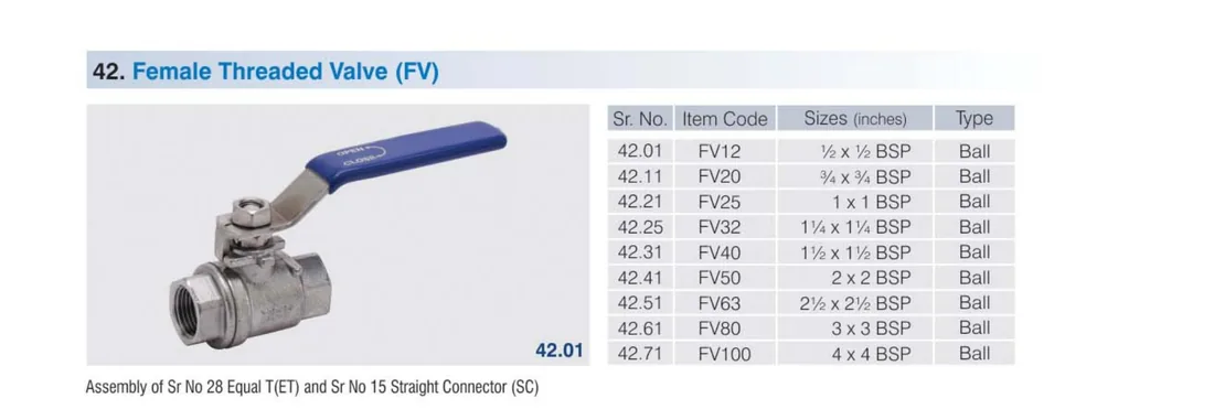
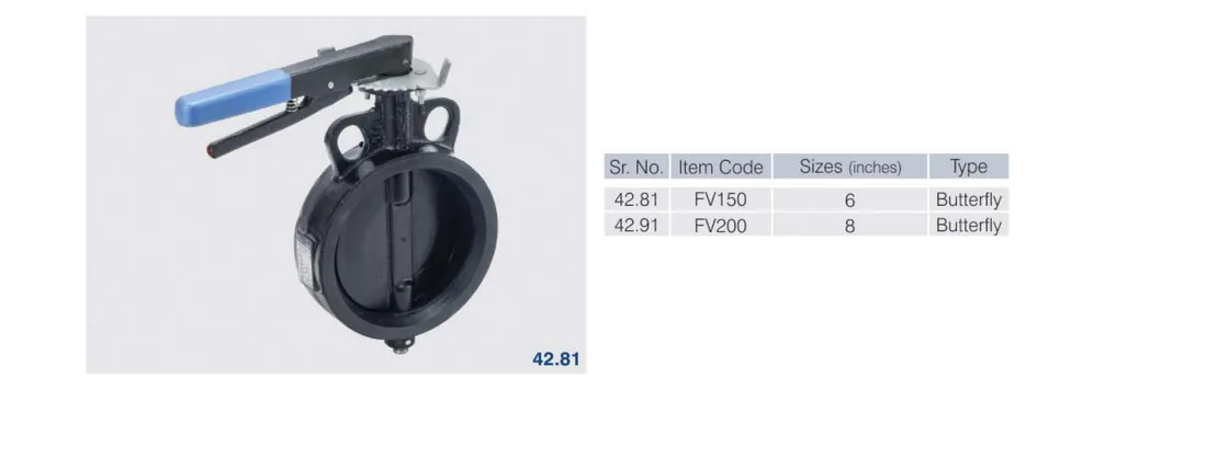
7. Valves
Female Threaded Valve & Butterfly (FV)
FV · ½″–8″
Sr No
Item Code
Size
Type
42.01
FV12
½″ × ½″ BSP
Ball
42.11
FV20
¾″ × ¾″ BSP
Ball
42.21
FV25
1″ × 1″ BSP
Ball
42.25
FV32
1¼″ × 1¼″ BSP
Ball
42.31
FV40
1½″ × 1½″ BSP
Ball
42.41
FV50
2″ × 2″ BSP
Ball
42.51
FV63
2½″ × 2½″ BSP
Ball
42.61
FV80
3″ × 3″ BSP
Ball
42.71
FV100
4″ × 4″ BSP
Ball
42.81
FV150
6″
Butterfly
42.91
FV200
8″
Butterfly
Product photo & technical drawing
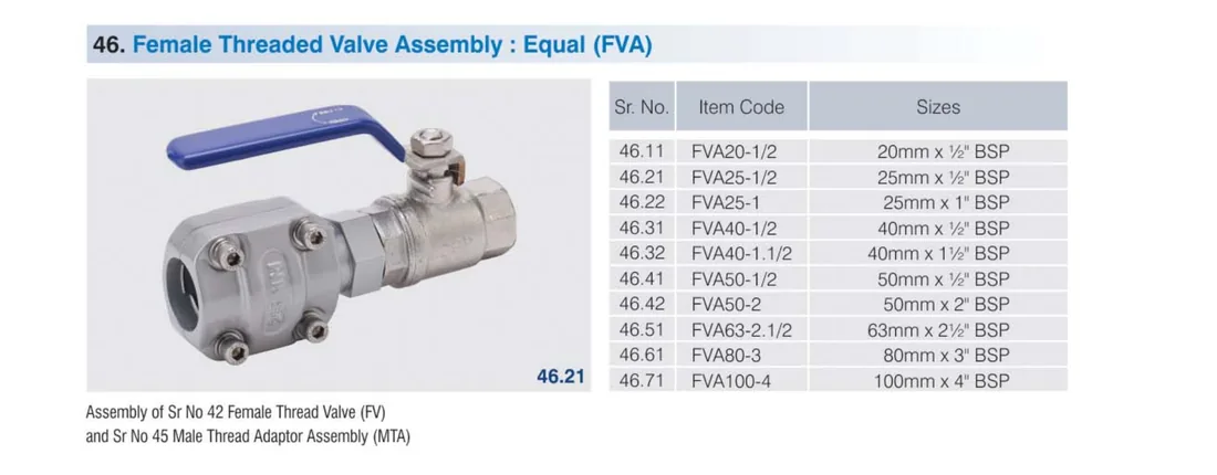
Female Threaded Valve Assembly (FVA)
FVA
Valve pre-assembled with connector & adaptor.
Sr No
Item Code
Size
46.11
FVA20-1/2
20mm × ½″ BSP
46.21
FVA25-1/2
25mm × ½″ BSP
46.22
FVA25-1
25mm × 1″ BSP
46.31
FVA40-1/2
40mm × ½″ BSP
46.32
FVA40-1.1/2
40mm × 1½″ BSP
46.41
FVA50-1/2
50mm × ½″ BSP
46.42
FVA50-2
50mm × 2″ BSP
46.51
FVA63-2.1/2
63mm × 2½″ BSP
46.61
FVA80-3
80mm × 3″ BSP
46.71
FVA100-4
100mm × 4″ BSP
Product photo & technical drawing
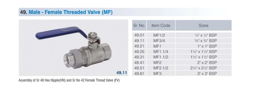
Male–Female Threaded Valve (MF)
MF · ½″–3″
Sr No
Item Code
Size
49.01
MF1/2
½″ × ½″ BSP
49.11
MF3/4
¾″ × ¾″ BSP
49.21
MF1
1″ × 1″ BSP
49.25
MF1.1/4
1¼″ × 1¼″ BSP
49.31
MF1.1/2
1½″ × 1½″ BSP
49.41
MF2
2″ × 2″ BSP
49.51
MF2.1/2
2½″ × 2½″ BSP
49.61
MF3
3″ × 3″ BSP
Product photo & technical drawing
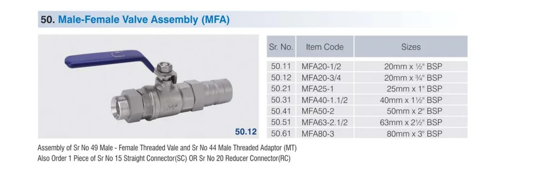
Male–Female Valve Assembly (MFA)
MFA
Sr No
Item Code
Size
50.11
MFA20-1/2
20mm × ½″ BSP
50.12
MFA20-3/4
20mm × ¾″ BSP
50.21
MFA25-1
25mm × 1″ BSP
50.31
MFA40-1.1/2
40mm × 1½″ BSP
50.41
MFA50-2
50mm × 2″ BSP
50.51
MFA63-2.1/2
63mm × 2½″ BSP
50.61
MFA80-3
80mm × 3″ BSP
Product photo & technical drawing
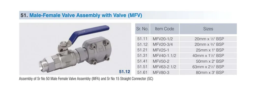
Male–Female Assembly w/ Valve (MFV)
MFV
Sr No
Item Code
Size
51.11
MFV20-1/2
20mm × ½″ BSP
51.12
MFV20-3/4
20mm × ¾″ BSP
51.21
MFV25-1
25mm × 1″ BSP
51.31
MFV40-1.1/2
40mm × 1½″ BSP
51.41
MFV50-2
50mm × 2″ BSP
51.51
MFV63-2.1/2
63mm × 2½″ BSP
51.61
MFV80-3
80mm × 3″ BSP
Product photo & technical drawing
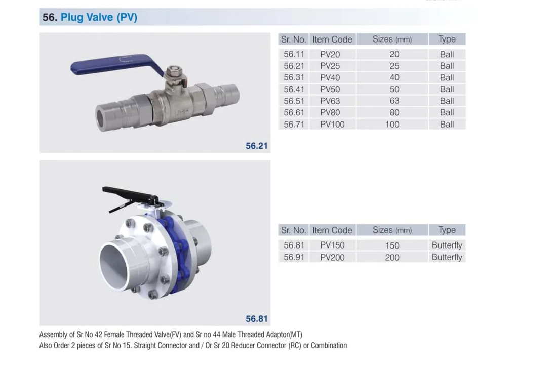
Plug Valve (PV)
PV · 20–200mm
Sr No
Item Code
Size (mm)
Type
56.11
PV20
20
Ball
56.21
PV25
25
Ball
56.31
PV40
40
Ball
56.41
PV50
50
Ball
56.51
PV63
63
Ball
56.61
PV80
80
Ball
56.71
PV100
100
Ball
56.81
PV150
150
Butterfly
56.91
PV200
200
Butterfly
Product photo & technical drawing
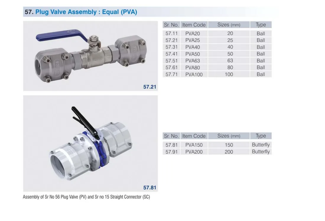
Plug Valve Assembly – Equal (PVA)
PVA · 20–200mm
Pre-fitted with straight connectors.
Sr No
Item Code
Size (mm)
Type
57.11
PVA20
20
Ball
57.21
PVA25
25
Ball
57.31
PVA40
40
Ball
57.41
PVA50
50
Ball
57.51
PVA63
63
Ball
57.61
PVA80
80
Ball
57.71
PVA100
100
Ball
57.81
PVA150
150
Butterfly
57.91
PVA200
200
Butterfly
Product photo & technical drawing
8. Threaded Adaptors & Nipples
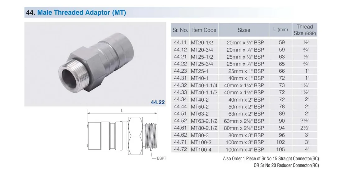
Male Threaded Adaptor (MT)
MT · ½″–4″
Sr No
Item Code
Size
L (mm)
Thread (BSP)
44.11
MT20-1/2
20mm × ½″
59
½″
44.12
MT20-3/4
20mm × ¾″
59
¾″
44.21
MT25-1/2
25mm × ½″
63
½″
44.22
MT25-3/4
25mm × ¾″
65
¾″
44.23
MT25-1
25mm × 1″
66
1″
44.31
MT40-1
40mm × 1″
72
1″
44.32
MT40-1.1/4
40mm × 1¼″
73
1¼″
44.33
MT40-1.1/2
40mm × 1½″
72
1½″
44.34
MT40-2
40mm × 2″
78
2″
44.44
MT50-2
50mm × 2″
78
2″
44.51
MT63-2
63mm × 2″
89
2″
44.52
MT63-2.1/2
63mm × 2½″
90
2½″
44.61
MT80-2.1/2
80mm × 2½″
94
2½″
44.62
MT80-3
80mm × 3″
96
3″
44.71
MT100-3
100mm × 3″
102
3″
44.72
MT100-4
100mm × 4″
105
4″
Product photo & technical drawing
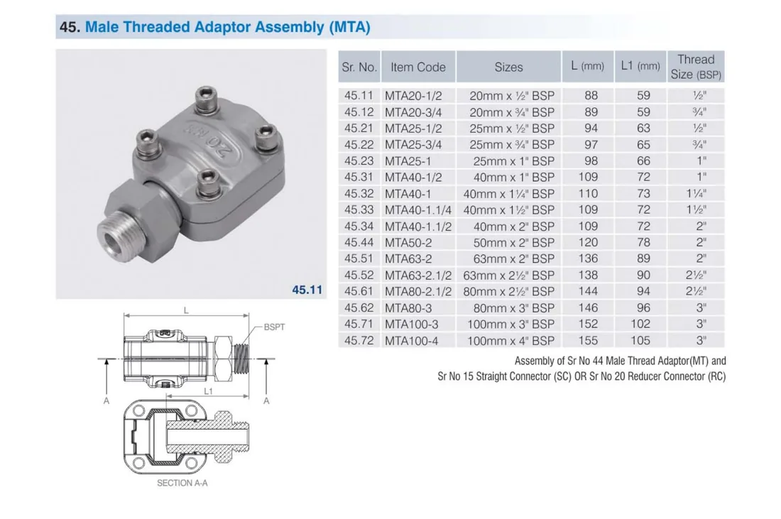
Male Threaded Adaptor Assembly (MTA)
MTA · ½″–4″
Sr No
Item Code
Size
L (mm)
L1 (mm)
Thread (BSP)
45.11
MTA20-1/2
20mm × ½″
88
59
½″
45.12
MTA20-3/4
20mm × ¾″
89
59
¾″
45.21
MTA25-1/2
25mm × ½″
94
63
½″
45.22
MTA25-3/4
25mm × ¾″
97
65
¾″
45.23
MTA25-1
25mm × 1″
98
66
1″
45.31
MTA40-1
40mm × 1″
109
72
1″
45.32
MTA40-1.1/4
40mm × 1¼″
110
73
1¼″
45.33
MTA40-1.1/2
40mm × 1½″
109
72
1½″
45.34
MTA40-2
40mm × 2″
109
72
2″
45.44
MTA50-2
50mm × 2″
120
78
2″
45.51
MTA63-2
63mm × 2″
136
89
2″
45.52
MTA63-2.1/2
63mm × 2½″
138
90
2½″
45.61
MTA80-2.1/2
80mm × 2½″
144
94
2½″
45.62
MTA80-3
80mm × 3″
146
96
3″
45.71
MTA100-3
100mm × 3″
152
102
3″
45.72
MTA100-4
100mm × 4″
155
105
4″
Product photo & technical drawing
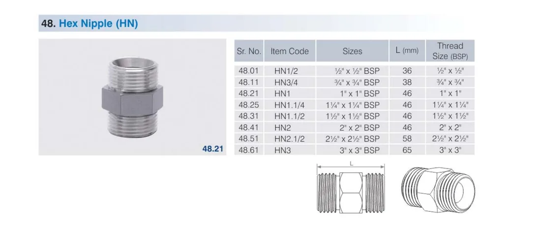
Hex Nipple (HN)
HN · ½″–3″
Male–male BSP nipple.
Sr No
Item Code
Size
L (mm)
48.01
HN1/2
½″ × ½″ BSP
36
48.11
HN3/4
¾″ × ¾″ BSP
38
48.21
HN1
1″ × 1″ BSP
46
48.25
HN1.1/4
1¼″ × 1¼″ BSP
46
48.31
HN1.1/2
1½″ × 1½″ BSP
46
48.41
HN2
2″ × 2″ BSP
46
48.51
HN2.1/2
2½″ × 2½″ BSP
58
48.61
HN3
3″ × 3″ BSP
65
Product photo & technical drawing
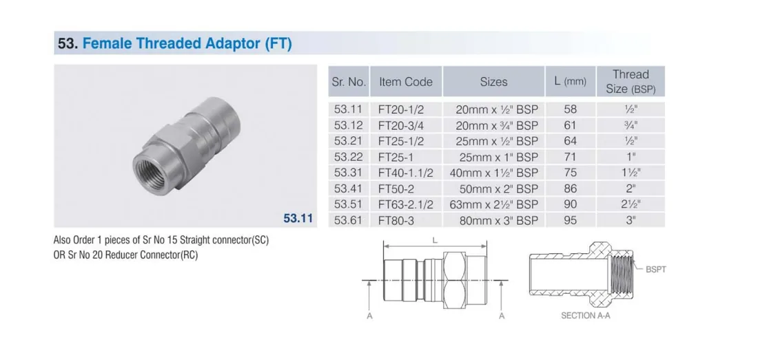
Female Threaded Adaptor (FT)
FT · ½″–3″
Sr No
Item Code
Size
L (mm)
Thread (BSP)
53.11
FT20-1/2
20mm × ½″
58
½″
53.12
FT20-3/4
20mm × ¾″
61
¾″
53.21
FT25-1/2
25mm × ½″
64
½″
53.22
FT25-1
25mm × 1″
71
1″
53.31
FT40-1.1/2
40mm × 1½″
75
1½″
53.41
FT50-2
50mm × 2″
86
2″
53.51
FT63-2.1/2
63mm × 2½″
90
2½″
53.61
FT80-3
80mm × 3″
95
3″
Product photo & technical drawing
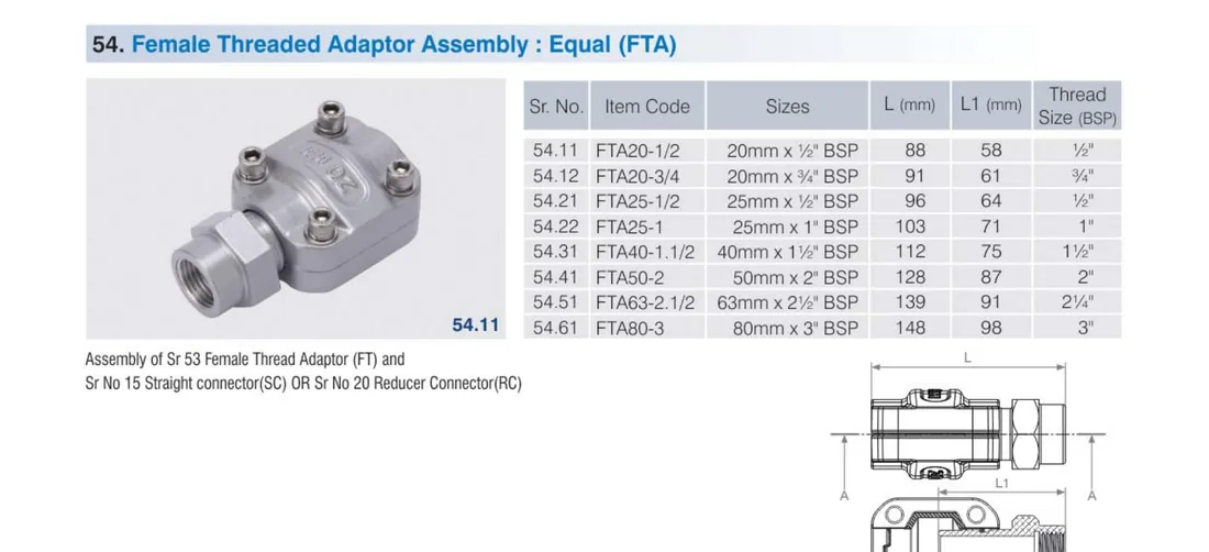
Female Threaded Adaptor Assembly (FTA)
FTA · ½″–3″
Sr No
Item Code
Size
L (mm)
L1 (mm)
Thread (BSP)
54.11
FTA20-1/2
20mm × ½″
88
58
½″
54.12
FTA20-3/4
20mm × ¾″
91
61
¾″
54.21
FTA25-1/2
25mm × ½″
96
64
½″
54.22
FTA25-1
25mm × 1″
103
71
1″
54.31
FTA40-1.1/2
40mm × 1½″
112
75
1½″
54.41
FTA50-2
50mm × 2″
128
87
2″
54.51
FTA63-2.1/2
63mm × 2½″
139
91
2½″
54.61
FTA80-3
80mm × 3″
148
98
3″
Product photo & technical drawing
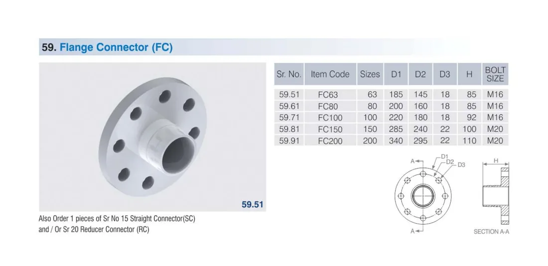
9. Flange Connectors
Flange Connector (FC)
FC · 63–200mm
Sr No
Item Code
Size (mm)
D1 (mm)
D2 (mm)
D3 (mm)
H (mm)
Bolt
59.51
FC63
63
185
145
18
85
M16
59.61
FC80
80
200
160
18
85
M16
59.71
FC100
100
220
180
18
92
M16
59.81
FC150
150
285
240
22
100
M20
59.91
FC200
200
340
295
22
110
M20
Product photo & technical drawing
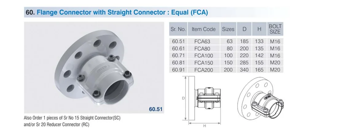
Flange + Straight Connector (FCA)
FCA · 63–200mm
Flange pre-assembled with straight connector.
Sr No
Item Code
Size (mm)
D (mm)
H (mm)
Bolt
60.51
FCA63
63
185
133
M16
60.61
FCA80
80
200
135
M16
60.71
FCA100
100
220
142
M16
60.81
FCA150
150
285
155
M20
60.91
FCA200
200
340
165
M20
Product photo & technical drawing
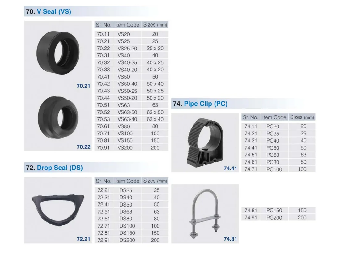
10. Seals, Clips & Flexible Hose
V-Seal (VS)
VS · 20–200mm
Replacement O-ring seal (equal & reducing).
Sr No
Item Code
Size (mm)
70.11
VS20
20
70.21
VS25
25
70.22
VS25-20
25 × 20
70.31
VS40
40
70.32
VS40-25
40 × 25
70.33
VS40-20
40 × 20
70.41
VS50
50
70.42
VS50-40
50 × 40
70.43
VS50-25
50 × 25
70.44
VS50-20
50 × 20
70.51
VS63
63
70.52
VS63-50
63 × 50
70.53
VS63-40
63 × 40
70.61
VS80
80
70.71
VS100
100
70.81
VS150
150
70.91
VS200
200
Product photo & technical drawing
Drop Seal (DS)
DS · 25–200mm
Sr No
Item Code
Size (mm)
72.21
DS25
25
72.31
DS40
40
72.41
DS50
50
72.51
DS63
63
72.61
DS80
80
72.71
DS100
100
72.81
DS150
150
72.91
DS200
200
Pipe Clip (PC)
PC · 20–200mm
Sr No
Item Code
Size (mm)
74.11
PC20
20
74.21
PC25
25
74.31
PC40
40
74.41
PC50
50
74.51
PC63
63
74.61
PC80
80
74.71
PC100
100
74.81
PC150
150
74.91
PC200
200
Flexible Hose Assembly (FHA)
FHA · 20–100mm
Flexible point-of-use drops.
Sr No
Item Code
Size
75.11
FHA20-1
20mm × 1 Mtr
75.12
FHA20-2
20mm × 2 Mtr
75.21
FHA25-1
25mm × 1 Mtr
75.22
FHA25-2
25mm × 2 Mtr
75.31
FHA40-1
40mm × 1 Mtr
75.32
FHA40-2
40mm × 2 Mtr
75.41
FHA50-1
50mm × 1 Mtr
75.42
FHA50-2
50mm × 2 Mtr
75.51
FHA63-1
63mm × 1 Mtr
75.52
FHA63-2
63mm × 2 Mtr
75.61
FHA80-1
80mm × 1 Mtr
75.62
FHA80-2
80mm × 2 Mtr
75.71
FHA100-1
100mm × 1 Mtr
75.72
FHA100-2
100mm × 2 Mtr
Product photo & technical drawing
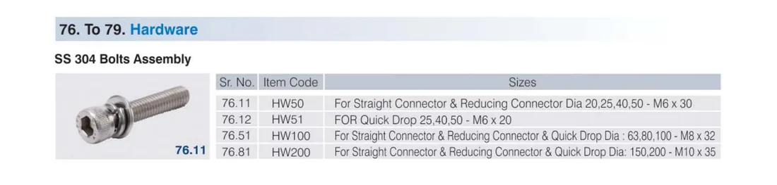
11. Hardware & Accessories
Mounting Hardware
HW · TBMB · IEM · WB
Bolts, T-bolts, expansion bolts & wall brackets.
Sr No
Item Code
Description
76.11
HW50
SS304 bolt set — SC/RC Ø20,25,40,50 — M6 × 30
76.10
HW51
SS304 bolt set — Quick Drop 25,40,50 — M6 × 20
76.51
HW100
SS304 bolt set — SC/RC/QDA Ø63,80,100 — M8 × 32
76.81
HW200
SS304 bolt set — SC/RC/QDA Ø150,200 — M10 × 35
76.91
TBMB-50
T-Bolt M8 × 50
76.92
TBMB-60
T-Bolt M8 × 60
76.93
TBMB-70
T-Bolt M8 × 70
76.96
IEM8
Iron Expansion Bolt M8
76.97
IEM10
Iron Expansion Bolt M10
78.11
WB300
Wall Support Bracket 300 mm
78.21
WB500
Wall Support Bracket 500 mm
78.31
WB1200
Wall Support Bracket 1200 mm
Product photo & technical drawing
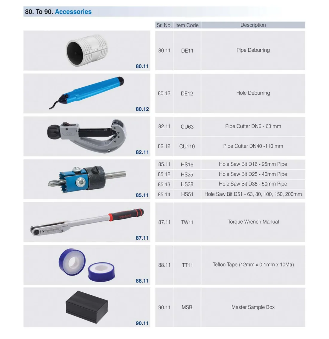
Installation Tools & Accessories
KTM · DE · CU · HS · TW · TT · MSB
Sr No
Item Code
Description
79.11
KTM8
Knot Tie M8
80.11
DE11
Pipe Deburring tool
80.12
DE12
Hole Deburring tool
82.11
CU63
Pipe Cutter DN6–63 mm
82.12
CU110
Pipe Cutter DN6–110 mm
85.11
HS16
Hole-saw bit D16 — 25 mm pipe
85.12
HS25
Hole-saw bit D25 — 40 mm pipe
85.13
HS38
Hole-saw bit D38 — 50 mm pipe
85.14
HSS1
Hole-saw bit set — 63, 80, 100, 150, 200 mm
87.11
TW11
Torque Wrench (manual)
88.11
TT11
Teflon Tape (12mm × 0.1mm × 10 Mtr)
90.11
MSB
Master Sample Box
Product photo & technical drawing
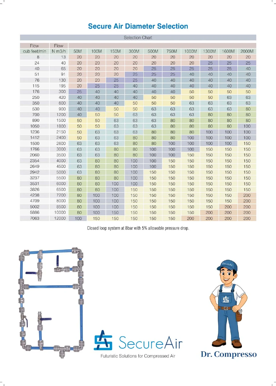
Diameter Selection Chart
Find your air demand on the left (CFM or m³/h), read across to your total pipe-run length, and the cell gives the recommended SecureAir pipe diameter (mm). Based on a closed-loop system at 8 Bar with 5% allowable pressure drop. For an exact design, request a free sizing from our engineers.
SecureAir Compressed Air Pipe Diameter Selection (mm) — Closed loop @ 8 Bar, 5% pressure drop
Flow (CFM)
Flow (m³/h)
50 M
100 M
150 M
300 M
500 M
750 M
1000 M
1300 M
1600 M
2000 M
8
13
20
20
20
20
20
20
20
20
20
20
24
40
20
20
20
20
20
20
20
25
25
25
40
65
20
20
20
20
25
25
25
25
25
40
51
91
20
20
20
25
25
25
40
40
40
40
76
130
20
20
25
25
40
40
40
40
40
40
115
195
20
25
25
40
40
40
40
40
40
40
176
300
25
40
40
40
40
40
50
50
50
50
250
420
40
40
40
40
50
50
50
50
63
63
350
600
40
40
40
50
50
50
63
63
63
63
530
900
40
40
50
50
63
63
63
63
63
80
700
1200
40
50
50
63
63
63
63
80
80
80
890
1500
50
50
63
63
63
80
80
80
80
80
1050
1800
50
50
63
63
80
80
80
80
80
100
1236
2150
50
63
63
63
80
80
80
100
100
100
1412
2400
50
63
63
80
80
80
100
100
100
100
1500
2600
63
63
63
80
80
100
100
100
100
150
1766
3000
63
63
80
80
100
100
100
150
150
150
2060
3500
63
63
80
80
100
100
150
150
150
150
2354
4000
63
80
80
100
100
150
150
150
150
150
2649
4500
63
80
80
100
100
150
150
150
150
150
2942
5000
63
80
80
100
150
150
150
150
150
150
3237
5500
80
80
80
100
150
150
150
150
150
150
3531
6000
80
80
100
100
150
150
150
150
150
200
3826
6500
80
80
100
150
150
150
150
150
150
200
4238
7200
80
100
100
150
150
150
150
150
200
200
4709
8000
80
100
100
150
150
150
150
150
200
200
5002
8500
80
100
150
150
150
150
150
200
200
200
5886
10000
80
100
150
150
150
150
150
200
200
200
7063
12000
100
100
150
150
150
150
200
200
200
200
Original SecureAir selection chart (closed-loop system at 8 Bar, 5% allowable pressure drop).
Get a SecureAir Quote & Free Sizing
Tell us your air demand and plant layout — Aamtron Group will size your ring main, build the bill of materials by item code, and quote supply or full turnkey installation across Qatar & the UAE.